News
13 May 2019
Wireless Voodoo – Not a Dark Art

Subscribe to CX E-News
WIRELESS
Wireless Voodoo – Not a Dark Art
by Fraser Walker.
Wireless in the world of audio is often referred to in dubious terms. It fails by way of voodoo, or works flawlessly as if by magic. All of this uncertainty is caused by the fact that we as humans have no means of detecting it. There is a huge hole in our senses between our range of hearing and the spectrum of visible light; and that space is full of electromagnetic energy that can make or break your show… however, despite all the myths and old wives tales there is no reason to consider wireless a dark art.
The first successful radio transmission was achieved in 1896, and by the time Woodstock rolled around in 1969 we had FM radio and colour TV. In the moment our burgeoning industry was figuring out how to achieve a large concert system, radio transmission was already a full-fledged commercial and military technology.
By the late 70s wireless microphones were finding their way onto stage, and the voodoo began to appear. Of course with the right RF engineering a huge number of these systems can work simultaneously… Olympic ceremonies, Eurovision and the NFL Super Bowl are a continual testament to this.
On the flip side undertaking no RF engineering at all with just a couple of wireless microphones will quickly turn into a disaster. Being audio related, help is often sought or expected from the audio crew, an engineer used to dealing with sound waves up to a few kilohertz.
The problems that present themselves at a few hundred megahertz are slightly different, however by considering they too are caused by the interaction of wavelengths, many of the prevalent issues can be overcome.
Speed of sound 343 m/s
Speed of electromagnetic radiation 299,792,458 m/s
1kHz Audio – 34cm
1GHz RF – 30cm
600MHz RF – 50cm
The main cause of wireless microphone voodoo is interference. The main cause of interference is using un-coordinated wireless frequencies, or by using a frequency that is part of a local TV channel.
Almost every manufacturer has software tools to enable you to avoid both of these common pitfalls – and whilst most audio engineers are familiar with the process, a common frustration is this: “I did the scan, I coordinated my frequencies and I still have dropouts at specific points on stage, why?!”
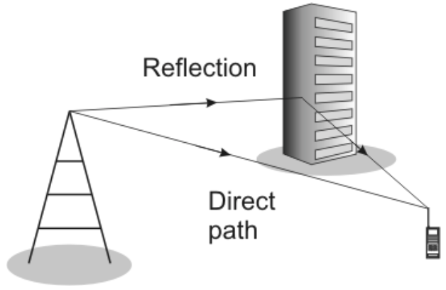
This leads us to the second cause of voodoo: Multipath propagation.
Most of our wireless equipment operates in the UHF range, and at those wavelengths, any metallic surface larger than a few centimetres will be reflective to RF energy. Most audio engineers are familiar with lumpy bass response caused by the differing arrival times from left and right subwoofer stacks. This is the same theory that causes nulls due to multipath propagation.
Nulls occur where there is a direct line of sight signal, and a reflected signal that has traveled a slightly longer path. This path length difference creates a time offset and thus a degree of phase cancellation occurs.
In a real world scenario, these reflective surfaces may be lighting truss uprights, scenic set elements or the truss supports of an outdoor stage.
There is a common misconception that these kinds of wireless dropouts can be fixed by increasing the transmitter power, however the cancellation will remain unchanged regardless of power. The only way to rectify multipath cancellation is to change the path length relationship between the transmitter and receiver.
Scenario: The band is on IEM, and using no wireless mics. Upon doing a walk test of the stage, there is a strong null on the lead singer’s frequency at their mic stand downstage centre. You can’t move stage centre. The singer’s pack is on 600.000Mhz, and a null is being caused by reflected energy arriving ½ wavelength delayed.
Moving the transmitting antenna just 20cm towards them will change the phase relationship at the IEM receiver and that null will be moved elsewhere. It should be noted that moving the transmitting antenna has changed the path length for all frequencies in use on stage.
Another option to overcome the null at the lead singers mic stand would be to change their frequency, using one of the spare frequencies from the coordination. This has the same affect as changing the physical path length, as the new frequency will have a different wavelength, therefore the reflection will have a different phase relationship at the IEM receiver.
Multipath propagation can be avoided by ensuring there are no reflective objects within the 2nd Fresnel zone between the transmitter and receiver, a topic beyond the scope of this article and purposefully avoided, as it is usually not achievable at most events.
The final major cause of voodoo is a lack of received power at the receiver.
Wireless receivers are working incredibly hard to capture what is left of a signal after it has endured the losses caused by antennas, air and cable. The front end of a receiver contains an amplifier to receive these weak signals, however this amplifier will also turn itself down when it encounters a strong signal to prevent itself from being damaged by overloading.
This is known as desensitisation.
For example a handheld microphone that is sitting on a stand next to your receiving antennas will severely reduce your ability to receive a weak signal from a mic located far away or otherwise obscured from the antennas.
Similarly, mounting your IEM transmit antenna to a stereo bar along with your receive antennas is a clean and fast way to use one mic stand at a festival and also a sure fire way to desensitize the mic receivers, particularly if you are smashing eight channels of 100mW from the transmitters to try and overcome a multipath issue. Give your receive antennas some freedom from strong radiation.
When using directional antennas, use that to your advantage by placing known sources of interference in the null points of your receive antennas.
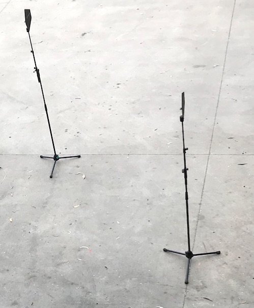
All antennas should be operating in a free field, theoretically 6x wavelength if space will allow it. This is around 3m for the range used in Australia.
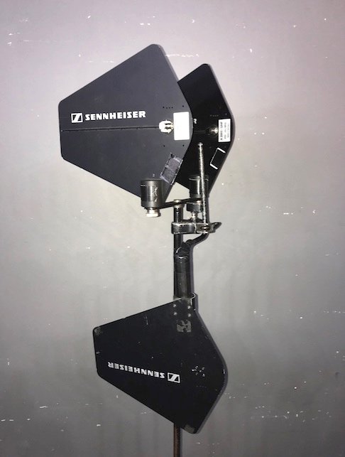
Diversity receiving antennas should be spaced at least 1x wavelength, to allow for differing path lengths to the transmitter. Where space does not permit spacing for multipath diversity, the antennas should be offset by 90degrees, thereby offering polarization diversity instead. (RF Venue Diversity Fin is an example of this)
You can’t see the radiation but you can visualise the antenna beamwidth in horizontal and vertical planes.
Using high-power transmit modes aimlessly only serves to increase the noise floor and create desensitization issues and should only be used where every other best practice has not allowed for enough power to be received.
Wireless belt packs worn on the body often suffer huge losses in radiated power due to skin contact conducting the energy from the transmitting antenna more readily than it can be transmitted into the air. This gets exponentially worse on sweaty skin.
Try and keep the belt pack high and dry, particularly the antenna – disposable latex gloves and lubricant free condoms are tools of the trade here. It is also one of the few times where a high power transmit mode can be used for good reason, offering comparable radiated power to a handheld microphone at standard output.
IEMs use the same transmission method as commercial FM radio. Developed in the 1960s when stereo was just catching on, it was imperative that any stereo transmission was also mono compatible. They achieved this by developing a multiplexed standard of modulation, known as FM MPX.
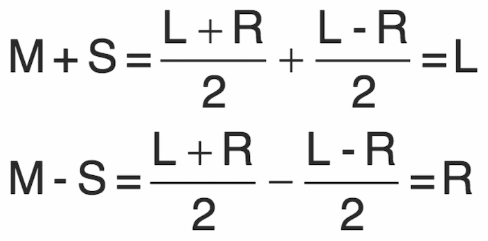
By employing the same mid/side encoding techniques known from microphone placements, mono compatibility was ensured with the ability to easily expand to stereo.
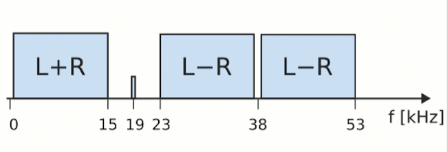
The MPX standard consists of three parts – a Mid component with a bandwidth of 40Hz to 15kHz, a pilot tone centered at 19kHz and the Side component from 23kHz to 53kHz. Where the receiver does not see a pilot tone, it demodulates to a mono compatible L+R signal. Where it sees a pilot tone it will demodulate a stereo signal by using the sum and difference of the two channels.
There are two important things to consider here. Whilst there is a LPF in the transmitter at 15kHz, it is not infinitely steep. There is a tendency to boost the “air” on vocals to overcome some of the occlusion that singers wearing IEM experience, however large amounts of HF boost can ultimately lead to the pilot tone being modulated inadvertently.
This leads to issues in the demodulation of the stereo signal – causing a lack of separation in stereo elements. The suggestion is there is nothing above 15kHz being received, so there is no need to boost any frequencies beyond that.
Thanks to digital consoles there is a good argument for having an additional LPF on all IEM mix outputs.
The second part to mastering this codec puzzle is to ensure strong mono compatibility in the transmitted stereo signal. Having large phase discrepancies between the left and right channel will cause artifacts when the receiver attempts to decode the stereo signal.
Usual culprits for this are that artificially wide sounding percussion stem coming from playback, or some enthusiastic usage of stereo widening on the monitor console. A little bit goes a long way, and once again, overdoing it will result in effectively collapsing the stereo image despite the overzealous attempts to widen it.
Another myth that needs to be dispelled is that frequencies in different ranges do not interact with each other.
It’s uncanny how often engineers familiar with intermodulation and frequency coordination throw it all out the window as soon as transmitters are spread across multiple frequency bands (i.e. Sennheiser A and G band). Intermodulation is well covered by many other articles, but remember that 500Mhz and 700Mhz will create a product at 600Mhz.
As most are aware, the entry price to wireless audio has been coming down at the same time that our available spectrum is shrinking. The end result is we have more frequencies trying to fit into a smaller space. That said, wireless is here to stay and having a strong grounding in the fundamentals of RF will make you a highly employable audio engineer well into the future.
Self-education is the key and we are lucky that Shure and Sennheiser both offer excellent training here.
And for those wanting to go the extra mile, remember that they are all just wavelengths, and white papers from GPS manufacturers and study guides for amateur radio are all applicable to having clean wireless at a gig.
CX Magazine – May 2019 – Australia and New Zealand’s only publication dedicated to entertainment technology news and issues – available in print and online. Read all editions for free or search our archive www.cxnetwork.com.au
© CX Media
Further reading from CX Magazine’s Wireless Feature – May 2019:
Shure Reveal Twinplex. Mission: Take on DPA – by Julius Grafton
Wireless Voodoo – Not a Dark Art – by Fraser Walker
In-Ear Monitoring – by Sennheiser’s Adam Karolewski
Clear-Com FreeSpeak II – by The P.A. People’s Chris Dodds
Signal Out of the Noise – by Simon Byrne
Is that a wireless intercom in your pocket? – by Jand’s Jeff MacKenzie
Antennas for Wireless Microphones – by Jand’s Jeff MacKenzie
The Politics of Wireless – by Simon Byrne
Wireless Recordings – by Andy Stewart
From the archive – Wireless Mics were a feature in Connections Magazine, March 1999: Radio Microphones (Sub-titled “How Did I Get Stuck With This Job!”) by John Matheson (includes a wireless systems Buyers Guide and Radio Spectrum Guide for Australia.)
Subscribe
Published monthly since 1991, our famous AV industry magazine is free for download or pay for print. Subscribers also receive CX News, our free weekly email with the latest industry news and jobs.

