LIGHTING
27 Jun 2024
Network Reliability & Flexibility with Dual Ethernet Ports
Subscribe to CX E-News
The Potential of Dual Ethernet Ports
Network-enabled devices are becoming more and more common as our world becomes increasingly connected. Using Ethernet is a common method for connecting equipment of potentially varying purposes together for management and/or data transmission. You may have noticed that some devices will have two Ethernet ports built in – have you ever wondered why? Or have you ever stopped to think what two ports could enable you to do in your installation?
Dual Ethernet is a common feature and is one that can enable a new level of flexibility and redundancy that you may have never thought possible. It offers a few advantages:
- 1. Flexibility to daisy-chain multiple devices, end-to-end
- 2. Reduce costs of cabling and required network ports in an installation
- 3. Flexibility in network designs and layouts
- 4. The ability to add a redundant network connection
Exploring Daisy-Chaining
You may have seen daisy-chaining in the context of power, possibly with dual IEC or dual powerCON connectors on a product, but if you’re not familiar with daisy-chaining Ethernet, you may ask yourself, why would daisy-chaining be useful for me, and when would I need to daisy-chain? There are many situations where daisy-chaining could be exactly what you need, but first, let’s look at what daisy-chaining is.
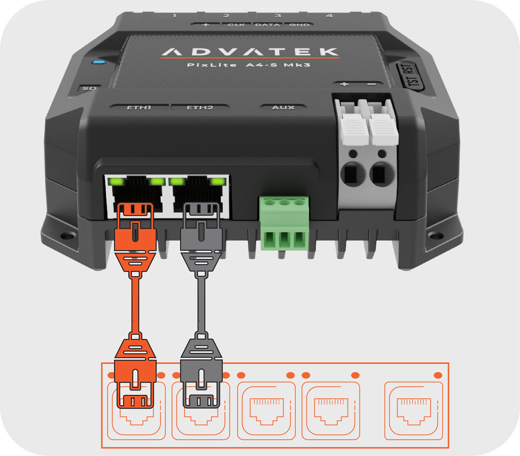
When a device has two Ethernet ports, this often means that they will act as a network switch, allowing you to have access to two Ethernet ports. When one port is used to connect the device to a network, the second port can be used to connect to the next device. By connecting multiple devices in this configuration, this builds what is known as a daisy-chain, where all devices in the chain are connected by network switches, allowing all devices to communicate with the connected network, and with each other. This cabling strategy resembles a DMX512 run, where one device daisy-chains to the next. The protocol in this case is different, but the cabling strategy is very similar.
This brings many possibilities for flexible connections in a system, including only needing to designate one network port on the main network switch to connect multiple devices. This allows connection of devices that are further from the switch than the 100-metre limit specified by Ethernet, and saves cost on cabling, as well as cost on network switches.
Even if unused, having a spare network port on these devices in an installation allows for contingency plans in the event where another device needs to be connected where there wouldn’t normally be a network port available. This can be useful if a lighting programmer arrives on site, and needs to connect an extra device or fixture, for example.
Similarly, the second Ethernet port could be used to daisy-chain to a testing computer, or to an operator-controlled device with a user interface. In short, daisy-chaining provides flexibility and options that wouldn’t normally be available if only one Ethernet port is present. It’s important to note that bandwidth across the daisy-chained line will increase as more devices are added. To ensure that communication is fast and reliable, the speed of the devices should be considered. Some devices only have Ethernet speeds of 100 Mb/s, which can be limiting depending on the required traffic. For any applications where large amounts of data are to be transmitted, a Gigabit speed device is best.
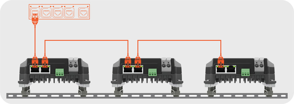
In the example diagram of daisy-chained devices, the dual Gigabit Ethernet ports on these pixel controllers are used to connect multiple devices, end-to-end. This is an example where the system has flexibility in connections and uses the Gigabit speeds to reliably transmit many lighting universes across the chain to all devices.
The Risk of Single Points of Failure
In a live environment, any single point of failure is a point of risk. If there is only one Ethernet cable connecting a device to the network, then that cable is solely responsible for communication to that device. A fault on this cable, like being accidentally disconnected, damaged, or trampled upon, means an offline device, and potentially a major issue in your lighting network.
In the context of a number of daisy-chained devices connected end-to-end, a fault in any single device in the chain is also a single point of failure. We’ll explore how to add redundancy to a chain of devices later in this article.
Redundancy with STP
One way to help is by adding in an additional network cable as redundancy, which removes the single point of failure. In the context of a single device, it may not be practical or required to have a backup network cable. This becomes more needed and practical when considering several daisy-chained devices. However, for the purposes of explaining the concept, we’ll first consider a single device.
The second network cable, acting as a redundant connection, provides a secondary path for network communication, in the event of a failure on the primary network cable.
The network switch will set one of these paths as active, and only activate the backup path when it needs to. The daisy chained network topology now has a secondary line, removing what was a single point of failure, and a source of risk.
To do this, there are some special abilities that the network switch must have. Managed network switches will usually feature an ability called Spanning Tree Protocol (STP), which is what is required for redundant connections.
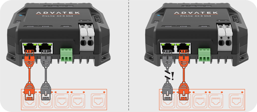
In the example below, Ethernet Ports 1 and 2 are both connected to the same pixel controller. By using STP, the switch can detect this as a network loop, and only activate one port.
The example below shows Port 1 as the active port, sending and receiving communication between the pixel controller and the rest of the network. When a fault occurs, the switch can detect that there is no longer a network loop, and so will activate Port 2, allowing for communication to continue, even though a fault has occurred on one of the cables.
It’s important to note that not all network switches will support STP, and those that do may need configuration to enable STP. If you’re looking for a switch that can support this, you’ll need to get a managed network switch, and check with the vendor to make sure it has STP supported. During configuration of the switch, refer to the vendor’s documentation on how to enable STP, and if Rapid Spanning Tree Protocol (RSTP) is available, this can provide an even faster response time.
Redundant Network Loop: Flexibility + Reliability
So far, we have seen the flexibility of daisy- chaining, and the reliability of a redundant Ethernet connection as two powerful features of having two Ethernet ports on a device. Now, let’s look at what happens when you combine these two together – the redundant network loop.
A chain of devices, connected via Ethernet, will begin at the network switch, and end at the last device in the chain. The second Ethernet port on the last device is currently not in use. Let’s see what happens if this port is connected back to a second port on the network switch.
In the diagram below, there are several devices connected to a network switch with STP enabled, and there is a redundant network cable connecting the second port on the final device to the network switch. By using STP, the switch detects a network loop, and so will only activate one of the ports, in this case assume it activated Port 1.
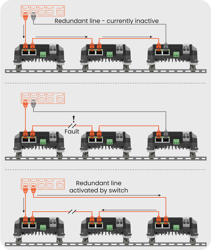
When a fault occurs on any single Ethernet cable in the chain, or on any single device in the chain, the switch detects the loop is no longer present, and so now it activates Port 2. At that point in time, Port 1 is used as a communication line for any devices before the fault, and Port 2 for any devices after the fault. Even though there has been a fault on a cable or in a device, the presence of the redundant network loop has allowed communication to continue for all devices in the physical chain.
By implementing a redundant network loop with dual Ethernet port devices, this provides both flexibility for daisy-chaining devices, and added reliability with a redundant connection to protect against a single fault. In a real-world installation, implementing this additional redundant connection would usually be relatively simple and cost-effective, only relying on one extra cable and one extra port on your managed network switch. A small addition to your installation, yet it could be a game-changer when it matters most!
Subscribe
Published monthly since 1991, our famous AV industry magazine is free for download or pay for print. Subscribers also receive CX News, our free weekly email with the latest industry news and jobs.