News
17 Jan 2022
With great power comes great responsibility

Subscribe to CX E-News
(and potential problems)
Walking along the top of a cliff looking over the ocean and enjoying the spectacular view is just one of the many ways to enjoy our amazing country. As long as your eyes are wide open and there is a safety rail, this activity is both safe and enjoyable.
Would that activity still be safe if you were blindfolded and the safety rails were removed? Of course not, as you would have no idea if you were 10m or 10mm from the edge of the cliff. At any moment you could step out over the edge with no warning.
Modern power distribution can be a bit like this. Things go wrong but we cannot always see why. Most of us understand over-current faults, but when it comes to earth leakage, we generally have little knowledge of what causes it, and that there is almost always earth leakage occurring in our rigs even when there is nothing wrong.
Have you ever been on a gig and had a circuit breaker or RCD trip for no logical reason? During set-up have you ever turned on a breaker and had it immediately trip out, but at the next gig with the exact same load, it worked perfectly first time? Have you prepped and tested a rig in the factory, only to have mysterious breaker trips when it is rigged in the real venue?
The company I work for has spent the last 18 months of lockdown looking into these questions, as many of our customers reported these as common problems that they did not understand. This article is the first in a series that will share this knowledge with you so that you can provide a better show to your clients.
Let’s start with a few facts that may surprise you.
• Every switch-mode power supply leaks some current to earth in normal operation.
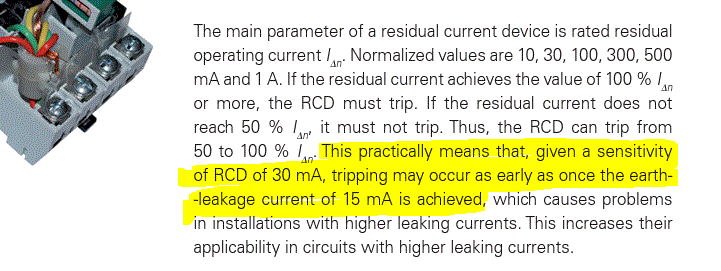
• The AS3000 wiring rules Section 2.6.2.1 states: RCDs may operate at any value of residual current in excess of 50% of the rated residual current. This means a 30mA RCD/RCBO can trip with an earth leakage current flow as low as 15mA!
• Long cable runs, particularly multi-core cables generate additional earth leakage currents.
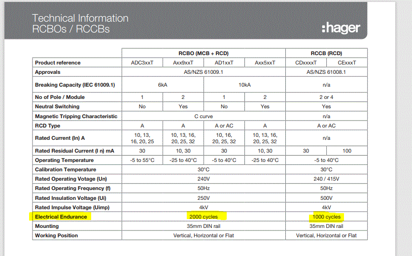
• MCBs, RCDs and RCBOs are not designed to be used as switches. As per the chart below, Hager rate their RCBO for 2,000 cycles and their RCDs for only 1,000 cycles (a cycle is turning the device on/off/on).
If we go back to when I started working in the industry (1980s), life was simple. Circuit protection was almost always a fuse and almost all electronic equipment used a transformer, which was mostly a resistive load.
Fuses were great. When a standard glass fuse blew, you could look inside and deduce how it blew. If a fuse had a short piece of wire at each end that did not meet in the middle, the fault was a minor overcurrent. If the inside of the glass was covered in blue/black residue then the fault was a dead short.
The one big disadvantage was the myriad of variants and ratings. In simple glass/ceramic fuses alone there were multiple sizes (3AG, 5AG, M205, BS1362) as well as different speed ratings (F for fast, T for slow) and of course different currents (1A, 2A, 3.15A, 5A, 10A, 15A, etc). There were also cartridge and HRC (High Rupture Current) fuses, which were much larger and massively more expensive. I had over 100 spare glass fuses in my toolbox, all organised in 35mm film canisters, but I was still caught out on occasions without an exact matching replacement.
As we moved into the 1990s, most power distribution systems thankfully got rid of fuses and replaced them with MCBs. At the same time a lot of amplifiers, CRT monitors (remember those things?), smoke machines and other equipment replaced their fuses with push button circuit breakers. It was no longer possible to easily work out why they tripped, but at least they could be reset quickly to get back up and running once you did find the problem.
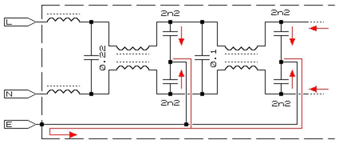
With the arrival of the new millennium things changed again. Now we must have RCDs for protection against earth leakage faults, as well as MCBs for over current protection. Transformers have joined the dinosaurs and been replaced by the compact and lightweight switch-mode power supply, which is a highly capacitive load. The problem with a capacitive load is that it creates mains disturbances which need to be filtered out. This filter results in earth leakage currents.
Can you spot the problem?
We now use power supplies that generate earth leakage at the same time as we have added protection devices that trip in the presence of earth leakage currents.
With the legal and OH&S requirement to include RCD protection into our systems, manufacturers started adding a single RCD to the input of a power distro unit. This was quickly replaced by an RCD per phase, to reduce the number of channels lost when a fault occurred. Then when compact RCBOs (combined MCB + RCD) appeared everyone started to use these units so that a fault only took out one output.
The problem with an RCBO is that when it trips you have no idea if the fault was a minor overcurrent, a dead short, or a small/large earth leakage fault. Can you see that blindfold starting to block your view?

To make matters worse no one knows how much ELC any device generates. Every product specification sheet shows the conventional current draw (eg. 8A @ 230v) but I have yet to see any specification sheet that includes the ELC load (eg. 3.5mA @ 230v). Every competent tech can instantly work out that they can connect 20 x 0.5A devices to a 10A circuit breaker without an issue. However, they have no idea if each device leaks 0.1mA or 3mA to earth, making it impossible to know if they will trip the RCD or not.
They could measure the ELC of each individual device with a specialised test rig, document it and then use that information to make an informed decision, but they still don’t know if the RCD will trip at 15, 20 or 30mA. As stated earlier, the ELC will increase by an unknown amount if the device is connected at the end of a 50-100m multi-core cable. The relative humidity can also have an effect on the amount of ELC, days of high humidity will result in an increased amount of ELC flowing.
By now you are truly ‘flying blind’. You can’t see the problem and you don’t know whether you are safely back from the edge of the cliff or about to step over the edge.
What you really need is a safety fence to stop you getting too close to the edge. One common solution is to connect an increasing number of devices until you finally trip the RCD/RCBO, then reduce the count by 20%. This is how most production companies I have talked to do it. However, none of them did it on the end of a multi-core cable or noted the relative humidity when doing the test.
I work for LSC Control Systems, who manufacture power distribution systems for audio, video and lighting, hence the current research project. The RnD team has been investigating the wonderfully wicked ways of RCDs and RCBOs and it has been extremely educational. On numerous occasions, just as we thought we finally understood everything someone would make another discovery which changed our understanding.
One of these ‘lightbulb’ moments was when we realised that an MCB and an RCD work in exactly opposite ways when it comes to the rating. A 10A MCB will not trip unless the load is greater than 10A. A typical C-curve MCB doesn’t trip unless the load exceeds 1.13 times the rating, meaning you can probably run 11A through it all day. With a load of 1.5 times the rating (15A) it should trip within 40-400 seconds. Only if the fault is greater than 6-12 times the rating then it will trip within 1/10th of a second.

An RCD is the exact opposite. It must trip with a load of less than 30mA and it must trip very quickly (within 300mS for a 30mA device, far less for a 10mA unit). Due to the manufacturing tolerances this means that the engineers design a 30mA RCD to trip at a much lower current, to be sure that it will always trip before 30mA. If the manufacturing tolerances are +/- 20% then this would require an RCD to be designed to trip at 24mA. This would mean a +20% unit would still trip out at 28.8mA, but a -20% device would trip at 19.2mA. The fact that the AS3000 standard allows them to go as low as 15mA tends to suggest that manufacturing tolerances are worse than +/-20%. This is confirmed in this excerpt from an Eaton Application Guide for Residual Current Devices.
Don’t get caught out thinking that you can connect 15 x 2mA devices to a 30mA RCD and expect it to work. You may not even be able to connect eight devices; it all depends on the tripping point of each individual RCD. In theory plugging a 16mA load into outlet #1 or #5 of a cheap power distro may cause it to always trip, but plugging it into outlets #2, #3, #4 or #6 could work perfectly. Not ideal when under pressure to get things going during setup. Add to this the fact that you probably don’t know that exact ELC load (has the humidity changed?) and you have the makings of many sleepless nights hoping that nothing trips on the opening night.
That’s all for this month. Next issue we will dive into inrush currents, earth leakage frequency and look at ways of mitigating the risks to your show created by the issues raised in this article.
Glossary
MCB – Miniature Circuit Breaker.
Any small circuit breaker with a low breaking capacity (e.g. 8kA) and a current rating less than 100A. Can be DINrail mounted, push button or other physical arrangement.
MCCB Moulded Case Circuit Breaker.
These are the large ‘master’ breakers you see in switchboards. They are usually 3-phase devices and rated for more than 100A. The major difference between an MCCB and an MCB is the fault current rating. An MCCB can disconnect a much higher current than an MCB.
RCD – Residual Current Device
A protection device that disconnects the power when the earth leakage current exceeds the specified rating.
RCBO – Residual Current Breaker with Overload protection
A combined MCB + RCD. These can be single phase or 3-phase. Single phase devices are usually in a single DIN width module (~18mm wide).
ELC – Earth Leakage Current
Any current that flows from the active to earth instead of through the neutral conductor.
GFI – Ground Fault Interupter
Another name, commonly used in America and Canada, for an RCD.
ELCB – Earth Leakage Circuit Breaker.
Yet another name for an RCD. Originally this referred to a voltage triggered device, but now occasionally used as a generic term for either a voltage or current triggered device.
More reading
Here are two articles that are a great read if you want to learn more:
The basics of RCDs
Why do Switch-mode power supplies generate earth leakage?
https://www.meanwelldirect.co.uk/glossary/what-is-leakage-current/
Subscribe
Published monthly since 1991, our famous AV industry magazine is free for download or pay for print. Subscribers also receive CX News, our free weekly email with the latest industry news and jobs.


